
Telecoms and networking equipment — routers, switches, line cards, optical transceivers and port panels — relies on large numbers of status and indicator LEDs to show power, link, activity and fault. On a dense board these can run to dozens or even hundreds of LEDs, each showing a specific color so the state of the equipment can be read at a glance.
A link LED showing the wrong color, or an activity LED that doesn't match its neighbors, can send the wrong signal to whoever is installing or diagnosing the equipment in the field. With so many LEDs on one board, a single incorrect indicator is easy to miss on a visual check but misleading in service.
Feasa products can test these boards at multiple points throughout the production process, and integrate readily into the in-circuit or functional test the board is already going through. Analysers can be daisy-chained to handle high-channel-count testing, keeping cost per channel down while still testing every LED. Status and indicator LEDs are typically handled by the Functional LED Analyser, and boards on ICT platforms by the ICT Analyser.

Find defects before customers do
A fault found at build costs far less than a return, recall or field repair

Protect brand reputation
A lighting defect that reaches the field reflects directly on the brand

Product consistency
Output should look the same from one unit to the next, and across a product range

Compliance
Specified and regulated products benefit from a documented result behind every unit

Objective, repeatable results
A measured value removes the subjectivity of a visual inspection

Keep pace with production
Fast, multichannel testing fits the line without becoming a bottleneck

Color & intensity testing
Confirms LEDs match one another and stay consistent from one unit to the next

Fast test times
Every LED read in a single cycle, in-line or off-line

Scalable multichannel testing
Up to 20 channels per analyser, daisy-chained for larger boards

Production-line integration
Integrates with test fixtures, PLCs and ICT systems for automated testing

Sequence & pattern characterization
Profiles blinking, sweeping or animated LED sequences over time

Data logging & results output
Every reading captured and exported for records and analysis
Instruments built for Telecoms & AI Infrastructure
Click any card to view the full product page.
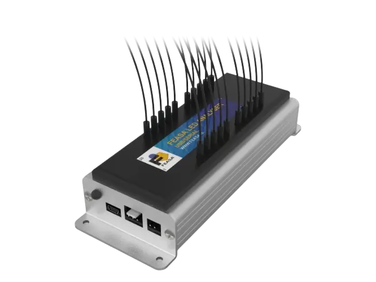 Functional LED Analyser
Multichannel color & intensity testing for production lines.
Learn more →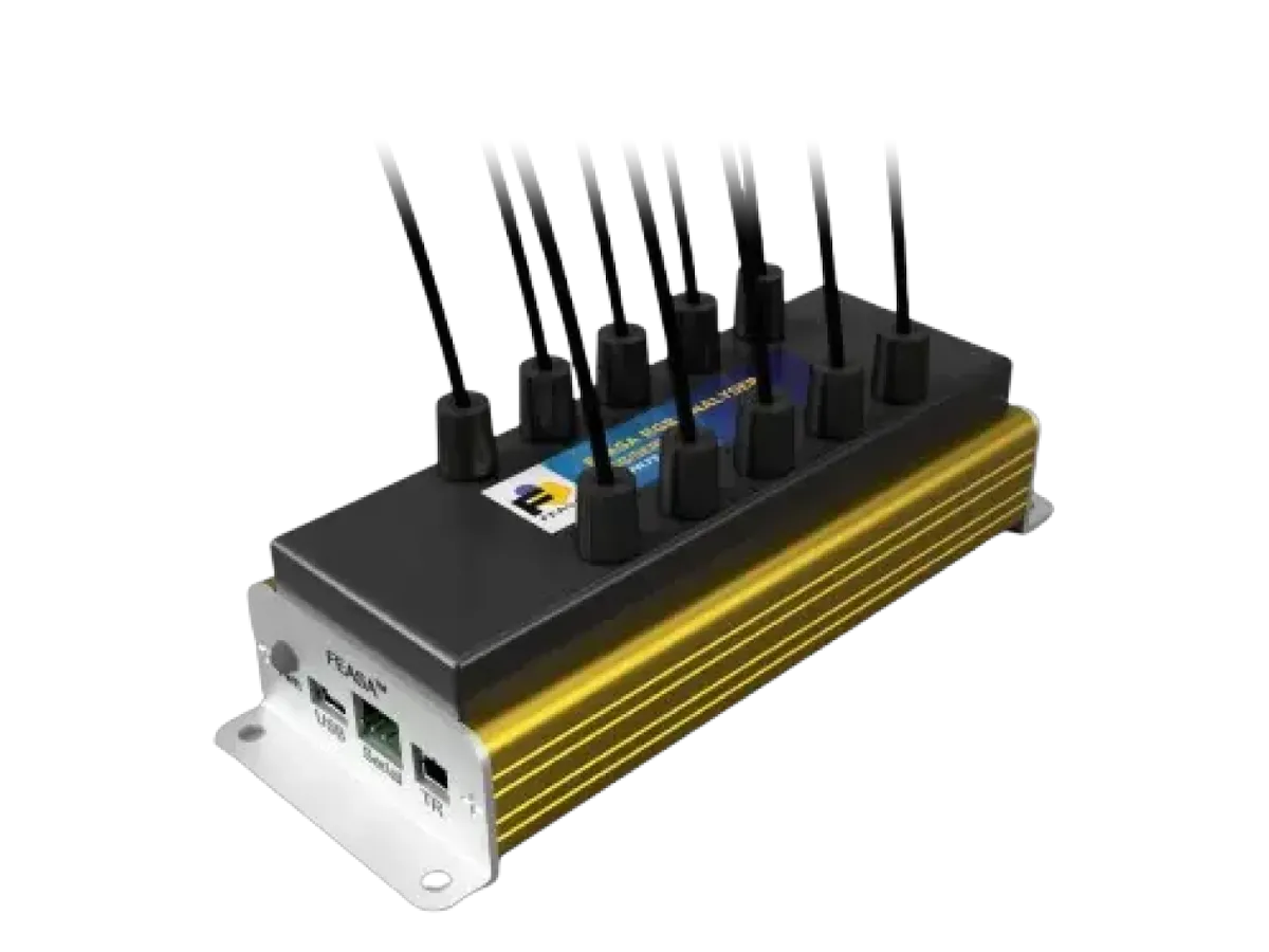 RGB LED Analyser
Purpose-built for RGB LEDs & backlit panels.
Learn more →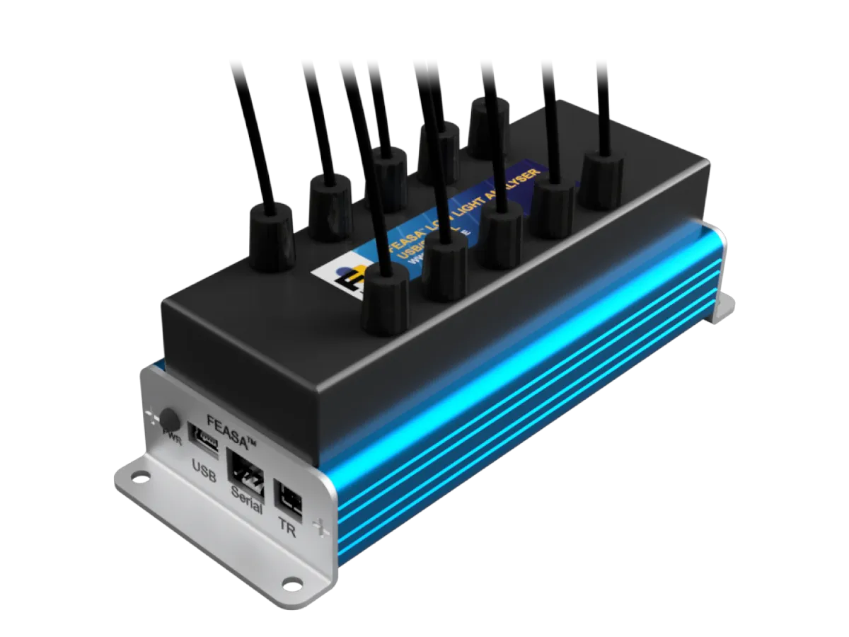 Low Light LED Analyser
For low-intensity LEDs and backlit switches.
Learn more →- High Brightness LED Analyser
For high-intensity LEDs such as headlights & beacons.
Learn more → 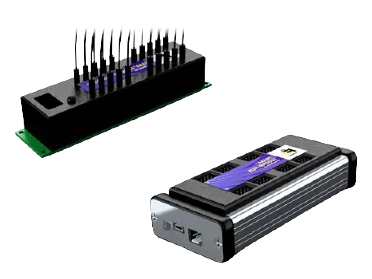 Legend System
Hub & satellite architecture testing up to 160 LEDs.
Learn more →- Life Tester LED Analyser
High & low temperature life testing, -65C to 125C.
Learn more →


Common Telecoms & AI indicator test scenarios
A closer look at how Feasa systems are applied to specific telecoms indicator measurement challenges.


Testing 90° side-view LEDs
Board-edge indicators mounted at 90° to the PCB are read in place using dedicated right-angle optical heads.
(x,y), wavelength and intensity are captured per indicator, as for any board position.

Verifying status LED color per operating state
Each indicator is captured for (x,y) and intensity.
Values are output for every driven state — power, link, activity and fault. Bi-color and RGB indicators are output per state so the customer can confirm the signaled status.

Characterizing link and activity blink behavior
On/off transitions are captured in rapid succession, giving an output profile over time.
Frequency and duty-cycle are output per indicator. A pattern-recognition feature handles repeating sequences.